Quantcast
Channel: pcDuino – LinkSprite Learning Center
Viewing all 15 articles
Browse latest View live

How to Enable Motion Triggered Cloud Recording for Deepcam

$
0
0

Deepcam plug and play security camera is a low cost WiFi camera that has vivid video quality. We showed how to use a pcDuino8 uno to detect the motion and upload the video clip to dropbox, so a user can watch all the events on smartphone.

Deepcam’s platform also offers a easy-to-use motion triggered cloud recording. In the following, we will show how to enable this excellent feature.

First, we need to login to mysnapcam.com website using our username and password to sign up for the cloud recording service.

After we sign up for the service, we can enable motion detection using APP. We have set up a test camera whose name is ‘test’:

IMG_5059

Click ‘Menu’ on the top left corner, and Select “Things” to configure the cameras:

IMG_5060


Select the camera “Test”, and adjust the sensitivities of motion detection and noise detection:

IMG_5061


Before the motion detection works, we need to make sure there is a SD card in the SD slot. If there is no SD card, please install one as below:

IMG_5064

We can also configure the time zone by “Menu-> Global Settings”:

IMG_5070


Now if there is any movement, when we click the ‘Alert’. We should be able to see them:

IMG_5063


IMG_5073


IMG_5078

IMG_5079


How to install FFMPEG for pcDuino8 Uno

$
0
0

FFMPEG is the great tool if you want to deal with video. In this tutorial, we show how to install this complicated tool on pcDuino8 Uno,

 Install H264 Support:

Enter the following commands:

$cd home/linaro
$git clone git://git.videolan.org/x264
$cd x264
$./configure --host=arm-unknown-linux-gnueabi --enable-static --disable-opencl
$make
$sudo make install


 Install AAC Support:

This step is optional. But as we will use ffmpeg to capture the rtsp stream from the deepcam, and save the video stream into mp4 file. So we will need to install this audio codec.

$cd /home/linaro
$git clone https://github.com/mstorsjo/fdk-aac.git
$cd fdk-aac

Before we move forward, we need to install dh-autoreconf tool:

$sudo apt-get install dh-autoreconf

Now we can begin the process by:

$ ./autogen.sh
$ ./configure --enable-shared --enable-static
$ make
$sudo make install
&sudo ldconfig -v

 Install FFMPEG:

When we install FFMPEG, we need to enable libx264 and libfdk-aac:

$cd /home/linaro
$git clone git://source.ffmpeg.org/ffmpeg.git
$cd ffmpeg
$sudo ./configure --arch=armel --target-os=linux --enable-gpl --enable-libx264 --enable-nonfree --enable-libfdk-aac
$make
$sudo make install


We can test if the installation is successful or not by typing ‘ffmpeg’.
Ref:

  1. http://www.jeffreythompson.org/blog/2014/11/13/installing-ffmpeg-for-raspberry-pi/


What is the correct pcDuino APT Package Server?

REAL TIME FACE DETECTION USING VIOLA-JONES AND CAMSHIFT IN PYTHON

$
0
0

As the title suggest’s, this blog mainly deals about real time Face Detection on a video (Last Week Tonight with John Oliver) using combined approach of Viola-Jones and CAMSHIFT. The prerequisites  are brief understanding about Viola-Jones face detection model using Haar features and CAMSHIFT algorithm for tracking object along with a fair amount of patience. If you are not interested in any explanation then here is the link to the code. Go get it!


Real Time Face Detection using Viola-Jones and CAMSHIFT in Python – I

pcDuino8 Uno_Interface_Diagram

Automatically connect a pcDuin8 Uno to a Wifi network

$
0
0

In this post I’ll quickly cover how you can set up your pcDuino8 uno to automatically connect to your wireless network. All you need is a WiFi-dongle.

Because the pcDuino8 uno only has one USB-port, you have to use an USB hub to expander USB port.

Requried

  1. pcDuino8 Uno
  2. USB Hub
  3. USB keyboard and mouse
  4. USB WiFi Dongle
  5. Screen with HDMI port and cable

Setting up WiFi connection

Start by booting the pcDuino8 uno, connected to a display and a keyboard. Open up the terminal and edit the network interfaces file:

sudo vim /etc/network/interfaces

This file contains all known network interfaces, it’ll probably have a line or two in there already.

Change the first line (or add it if it’s not there) to:

auto wlan0

Then at the bottom of the file, add these lines telling the pcDuino8 uno to allow wlan as a network connection method and use the /etc/wpa_supplicant/wpa_supplicant.conf as your configuration file.

allow-hotplug wlan0
iface wlan0 inet dhcp
wpa-conf /etc/wpa_supplicant/wpa_supplicant.conf
iface default inet dhcp

The next step is to create this configuration file.

Configuring WiFi connection

Open up the wpa_supplicant.conf file in the editor.

sudo vim /etc/wpa_supplicant/wpa_supplicant.conf

Again, some lines might already be present, just add the following.

ctrl_interface=DIR=/var/run/wpa_supplicant GROUP=netdev
update_config=1
network={
    ssid="YOUR_NETWORK_NAME"
    psk="YOUR_NETWORK_PASSWORD"
    proto=RSN
    key_mgmt=WPA-PSK
    pairwise=CCMP TKIP
    group=CCMP TKIP
    auth_alg=OPEN
}
  • proto could be either RSN (WPA2) or WPA (WPA1).
  • key_mgmt could be either WPA-PSK (most probably) or WPA-EAP (enterprise networks)
  • pairwise could be either CCMP (WPA2) or TKIP (WPA1)
  • auth_alg is most probably OPEN, other options are LEAP and SHARED

Make sure it works

Reboot the pcDuino8 uno and it should connect to the wireless network. If it doesn’t, repeat above steps or get help from an adult.

A big thanks to Automatically connect a Raspberry Pi to a Wifi network and pcDuino8 Uno section on LinkSprite’s Forum

How to install Linux header for pcDuino8 Uno

$
0
0

There is no source of linux-headers for pcDuino8 Uno, so it not easy to compile an kernel module for pcDuino8 uno. But before several days ago, LinkSprite released kernel source for pcDuino8 Uno, now it can get the Linux headers from this kernel source.

Required

  • pcDuino8 Uno
  • Host PC: Ubuntu 14.04(X86)

Kernel source

Steps

1. Prepare source code

Download the source code from github and create a directory called linux-headers-3.4.39 at /usr/src.

>sudo mkdir /usr/src/linux-headers-3.4.39
sudo cp ./linux-3.4 /usr/src/linux-headers-3.4.39 -r
sudo make O=/home/svn/linux-headers-3.4.39 sun8iw6p1smp_defconfig
sudo make O=/home/svn/linux-headers-3.4.39 modules_prepare

2. Create build soft link

cd /lib/modules/3.4.39
sudo ln -s /usr/src/linux-headers-3.4.39 build

3. Create Module.symvers

This file will be created when compile kernel source.

Go to your host PC Ubunt14.04(x64) and take the following steps to create Module.symvers.

3.1 Install tools

sudo apt-get install libc6:i386 libstdc++6:i386 libncurses5:i386 zlib1g:i386
sudo apt-get install gcc-arm-linux-gnueabihf
sudo apt-get install libncurses5-dev libncursesw5-dev device-tree-compiler u-boot-tools

3.2 Install gawk3.1.6

wget http://ftp.gnu.org/gnu/gawk/gawk-3.1.6.tar.bz2
tar -xvf gawk-3.1.6.tar.bz2
cd gawk-3.1.6
./configure
make
sudo make install

3.3 Build kernel

./build.sh config
    Welcome to mkscript setup progress
All available chips:
    0. sun6i
    1. sun8iw6p1
    2. sun9iw1p1
Choice: 1
All available platforms:
    0. android
    1. dragonboard
    2. linux
Choice: 2
not set business, to use default!
LICHEE_BUSINESS=
using kernel 'linux-3.4':
All available boards:
    0. eagle-p1
    1. eagle-p1-secure
    2. eagle-tvd-perf3
    3. pcduino8
    4. pcduino8-linux
Choice: 4

The Module.symvers will be created at linux-3.4 directory, and copy it to /usr/src/linux-headers-3.4.39 on pcDuino8 Uno.

4. Test

  • Create a hello.c file.
#include <linux/init.h>
#include <linux/module.h>

static int pcduino_hello_init(void)
{
    printk("Hello, pcDuino\n");
    return 0;
}

static void pcduino_hello_exit(void)
{
    printk("Bye, pcDuino\n");
}

MODULE_LICENSE("GPL");
MODULE_AUTHOR("latelan");
module_init(pcduino_hello_init);
module_exit(pcduino_hello_exit);
  • Create Makefile
KDIR := /lib/modules/3.4.39/build  # Point to Linux Kernel Headers
PWD := $(shell pwd)

obj-m := hello.o

default:
    make -C $(KDIR) M=$(PWD) modules

clean:
    rm -rf *.o .*cmd *.ko *.mod.c .tmp_versions *.symvers *order
  • Compile and test
make
sudo insmod hello.ko
dmesg | tail -n 1
[ 1957.116615] hello,world.
sudo rmmod hello.ko
dmesg | tail -n 1
[ 1976.438055] goodbye world

The installation of Linux headers on pcDuino8 Uno is done! Thanks to Latelan.

Use pcDuino8Uno and 96board as Zigbee Gateway

$
0
0

LinkSprite released a family of zigbee sensors for home automation and a zigbee gateway module to control these sensors.

In this tutorial, we show how to use pcDuino8 Uno  or 96 boards with the zigbee gateway module to work as a zigbee gateway.


Create a device on linksprite.io:

(1) Login to http://www.linksprite.io/signup to register for an account, and then login to the account:

Screen Shot 2016-05-12 at 10.39.22 PM

    (2) Create a DIY device:

        We can enter whatever names for Device Name, Group Name, please use 00 for the Device type, which means Custom device type:

Screen Shot 2016-05-12 at 10.41.57 PM

Click ‘Create’ to obtain the API key and device ID.

Screen Shot 2016-05-12 at 10.43.01 PM


Screen Shot 2016-05-12 at 10.43.10 PM


2.  Add api key and device ID to zigbee_usb.py. The zigbee.py can be found at our github.

Edit zigbee_usb.py, and modify deviceID and apikey:

Screen Shot 2016-05-12 at 10.48.56 PM

3. Launch the test program

    Connect the zigbee gateway with USB to TTL to pcDuino8 Uno, and copy zigbee_usb.py and pyserial-2.7 to pcDuino8 Uno, and install pyserial:

      Open pyserial-2.7, run:

     -> python setup install

   Wait for its finish, and run zigbee_usb.py

    -> python zigbee_usb.py

  Before the zigbee sensor device can be connected to the zigbee gateway, we need to press and hold the reset button for 2 seconds, and wait for the green LED to fast blink:

Screen Shot 2016-05-12 at 10.53.27 PM

 Add the zigbee sensor devices repeatedly, if the green LED stops blinking after reset, that mean the sensor has been added to the gateway successfully, and the program will return 0x02 8A 00. If now the sensor has been triggered, the program will return the current MAC address:

Screen Shot 2016-05-12 at 10.56.14 PM

The above shows that the current alarm device is door sensor, and the MAC address is the MAC address of the door sensor. Put the MAC address into the program as below:

Screen Shot 2016-05-12 at 10.57.32 PM

Add more device following the above procedure, and in this case,we only have two devices. Now we can go to www.linksprite.io to check the status:

Screen Shot 2016-05-12 at 10.58.42 PM


pcDuino3 Nano – Kernel Upgrade

$
0
0
This is the first of a series documenting my setup of a new home server with the Linksprite pcDuino3 Nano.  A listing for the entire series can be found here.  More information on the pcDuino3 Nano can be found at Linksprite’s website and thepcDuino website.

When I booted the fresh out of the box pcDuino3 Nano the kernel it booted from NAND was built on 10-15-2014. A check of the pcDuino3 Nano download page on the LinkSprite website showed that there was a more current version built on 12-5-2014.

I checked the version of the kernel running as shown below:

root@ubuntu:~# uname -a
Linux ubuntu 3.4.79+ #5 SMP PREEMPT Wed Oct 15 14:06:46 CST 2014 armv7l armv7l armv7l GNU/Linux
root@ubuntu:~#

The new kernel resolved the Aurduino-ish IDE corruption issue due to a serial port bug.  I figured before I got started with anything I would upgrade to the latest kernel.

On the pcDuino family of systems there are two methods for upgrading the software running from NAND.

    1. You can use the LiveSuit utility which loads software from a windows computer over usb.
    2. You can use the PhoenixCard utility which writes a specially formatted sd card.  This card is inserted in the system and when it is powered up it loads the new kernel.


I chose to use PhoenixCard.

Note: I have a USB TTL cable connected to the console pins or the pcDuino3 Nano.  While this isn’t a requirement to complete this process it helps to be able to see the messages as the print.

image_thumb[55]

1) The first step was to download the kernel image and the Ubuntu image which is done from thepcDuino3 Nano download page.  You also need to download a copy of PhoenixCard.

The version of PhoenixCard, Phoenix_V309, that is on the pcDuino3 Nano download page was flagged by Norton Internet security as a problem.  As a result I ended up using PhoenixCard_v310_20130618 which I found via Google here:https://drive.google.com/file/d/0B38hUt6ypQXDVTB6cWJXZ3ZGNkE/edit?usp=sharing

Save the files on your system.

image_thumb[30]

2) Extract PhoenixCard and run PhoenixCard.exe.

image_thumb[4]

3) You will get prompted to allow the program from an unknown publisher to make changes to your system.  You will need to say yes nd you will end up in PhoenixCard 3.10. PhoenixCard does an update check which starts out in Chinese but ends with a window in English.

image_thumb[29]

4) Click on the “Img File” button and select “cduino3_nano_a20_kernel_livesuit_20141205.img”.

image_thumb[19]

5) Check to make sure the disk in the disk window is correct and select “Burn”.  After the burn completes you will see the following messages in the Option window.

    • There is a note on the pcDuino3 Nano download page that says with some internal readers you may be a “Card Preprocess Failed !1012” due to the fact that they cannot write a partition table.
    • I ran into an interesting problem when my sd card’s lock tab ended up in the locked position.  PhoenixCard would say it could format the card but the burn would fail.  If the burn fails check your lock tab.


image_thumb[21]

6) Power off your pcDuino3 Nano and take the sd card out of your computer and put it into the pcDuino3 Nano’s sd slot.  Apply power to the pcDuino3 Nano.

While the kernel is loading LED 4 will flash.  Once the load is complete it will turn off.  When it does turn off the pcDuino3 Nano and remove the sd card.

7) Next you need to extract the Ubuntu files from the archive and write them to an sd card.

If you use the same sd card you used for the kernel load make sure you reformat the card before you write the ubuntu files to it.

You can do this with the PhoenixCard utility or another sd card formatting utility.

image_thumb[32]

8) Once the files have been written to the sd card take it out of your system and put it in the sd card slot in the pcDuino3 Nano and power up the system.  While the Ubuntu files are loading LED 3 will be on and LED 4 will flash.  When the load is finished both LED 3 and LED 4 will blink in unison.

9) Turn off the pcDuino3 Nano, remove the sd card and turn it back on.  It should boot into the updated kernel.

root@ubuntu:~# uname -a
Linux ubuntu 3.4.79+ #2 SMP PREEMPT Fri Dec 5 17:23:11 CST 2014 armv7l armv7l armv7l GNU/Linux
root@ubuntu:~#


Fro more details, please refer to the original post

http://digitalhacksblog.blogspot.hk/2014/12/pcduino3-nano-kernel-upgrade.html

pcDuino3 Nano – Ubuntu Updates

$
0
0
This is another in the series documenting my setup of a new home server with the Linksprite pcDuino3 Nano.  A listing for the entire series can be found here.  More information on the pcDuino3 Nano can be found at Linksprite’s website and thepcDuino website.

Now that we have completed the kernel upgrade the next step is to download and apply Ubuntu upgrades.  You may have caught that the date in the filename of the Ubuntu image was August 7, 2014.  That means that any updates that have been made available for Ubuntu since that time need to be applied to the system.

Ubuntu components are updated on an ongoing basis and this process can be used to update them on your system even if you haven’t updated the kernel.


Note

There is a lot of good information on www.pcduino.com.  On this topic you should check out the blog post Chapter 1: Hardware and Software Introductions of pcDuino.

You will need to be connected to the Internet for this process.

1) From a terminal window (or the console connection if you have one) you type in the sudo apt-get update.  If you get back a long stream of messages connecting to websites and downloading data as shown below that everything is working correctly.

ubuntu@ubuntu:~$ sudo apt-get update
Ign http://ppa.launchpad.net precise InRelease
Ign http://ports.ubuntu.com precise InRelease
Ign http://ports.ubuntu.com precise-security InRelease
Ign http://ports.ubuntu.com precise-updates InRelease
Hit http://ppa.launchpad.net precise Release.gpg
Hit http://ports.ubuntu.com precise Release.gpg
Get:1 http://ports.ubuntu.com precise-security Release.gpg [198 B]
Get:2 http://ports.ubuntu.com precise-updates Release.gpg [198 B]
Hit http://ppa.launchpad.net precise Release

<messages removed to save space>

Fetched 396 B in 8s (49 B/s)
Reading package lists... Done
W: Conflicting distribution: http://www.wiimu.com pcduino Release (expected pcduino but got )


The last line you get is warning that one of the repositories isn’t configured correctly this isn’t a fatal error and the process completes.

If you get back a slow stream of message that start with Err you are most likely not connected to the Internet.

ubuntu@ubuntu:~$ sudo apt-get update
Err http://www.wiimu.com pcduino InRelease

Err http://ppa.launchpad.net precise InRelease

Err http://ports.ubuntu.com precise InRelease

Err http://www.wiimu.com pcduino Release.gpg
  Temporary failure resolving 'www.wiimu.com'
Err http://ppa.launchpad.net precise Release.gpg
  Temporary failure resolving 'ppa.launchpad.net'
Err http://ports.ubuntu.com precise-security InRelease

^C


Confirming Internet Connectivity

You can confirm Internet connectivity using the ping command as shown below.  If you get a series or replies you are connected to the Internet.

ubuntu@ubuntu:~$ ping -c 5 www.google.com
PING www.google.com (74.125.196.106) 56(84) bytes of data.
64 bytes from yk-in-f106.1e100.net (74.125.196.106): icmp_req=1 ttl=246 time=24.0 ms
64 bytes from yk-in-f106.1e100.net (74.125.196.106): icmp_req=2 ttl=246 time=27.0 ms
64 bytes from yk-in-f106.1e100.net (74.125.196.106): icmp_req=3 ttl=246 time=25.2 ms
64 bytes from yk-in-f106.1e100.net (74.125.196.106): icmp_req=4 ttl=246 time=25.6 ms
64 bytes from yk-in-f106.1e100.net (74.125.196.106): icmp_req=5 ttl=246 time=24.6 ms

--- www.google.com ping statistics ---
5 packets transmitted, 5 received, 0% packet loss, time 4006ms
rtt min/avg/max/mdev = 24.003/25.340/27.070/1.039 ms

If the system appears to hang and eventually comes back as follows you do not have Internet connectivity.

ubuntu@ubuntu:~$ ping -c 5 www.google.com
ping: unknown host www.google.com

2) The update phase updates the list of current software from the to your computer but doesn’t apply any of the updates.  The next step sudo apt-get upgrade constructs a list of the packages that need updating and prompts you to confirm that you want to continue.  If you type a return or Y the process will continue.  If you type an n the process will stop without applying any updates.

ubuntu@ubuntu:~$ sudo apt-get upgrade
Reading package lists... Done
Building dependency tree
Reading state information... Done
The following packages have been kept back:
  libgrip0
The following packages will be upgraded:
  alsa-base alsa-utils apt apt-transport-https apt-utils base-files bash bc
  binutils bsdutils busybox-initramfs ca-certificates chromium-browser

<messages removed to save space>

  xserver-xorg-video-all xserver-xorg-video-nouveau
275 upgraded, 0 newly installed, 0 to remove and 1 not upgraded.
Need to get 216 MB of archives.
After this operation, 33.8 MB of additional disk space will be used.
Do you want to continue [Y/n]?

Once you continue the system will download all the updates and apply them on your system.  This process can take quite a bit of time.

<messages removed to save space>

Installing new version of config file /etc/pam.d/lightdm-autologin ...

Configuration file `/etc/init/lightdm.conf'
==> Modified (by you or by a script) since installation.
==> Package distributor has shipped an updated version.
   What would you like to do about it ?  Your options are:
    Y or I  : install the package maintainer's version
    N or O  : keep your currently-installed version
      D     : show the differences between the versions
      Z     : start a shell to examine the situation
The default action is to keep your current version.
*** lightdm.conf (Y/I/N/O/D/Z) [default=N] ?
Setting up lightdm-gtk-greeter (1.1.5-0ubuntu1.1) ...
Setting up openjdk-6-jre-lib (6b33-1.13.5-1ubuntu0.12.04) ...

<messages removed to save space>

Installing new version of config file /etc/rsyslog.conf ...
rsyslog stop/waiting
rsyslog start/running, process 12800
Setting up ifupdown (0.7~beta2ubuntu11.1) ...
Installing new version of config file /etc/init/network-interface.conf ...
Setting up network-manager-gnome (0.9.4.1-0ubuntu2.3) ...
Setting up resolvconf (1.63ubuntu16) ...
Installing new version of config file /etc/ppp/ip-down.d/000resolvconf ...
Installing new version of config file /etc/ppp/ip-up.d/000resolvconf ...
Setting up ubuntu-minimal (1.267.1) ...
Processing triggers for libc-bin ...
ldconfig deferred processing now taking place
Processing triggers for libgdk-pixbuf2.0-0 ...
Processing triggers for initramfs-tools ...
Processing triggers for resolvconf ...
ubuntu@ubuntu:~$

When you get back to the prompt all the updates have been applied.

For more details, please refer to original post

http://digitalhacksblog.blogspot.hk/2014/12/pcduino3-nano-ubuntu-updates.html

How to Use Professional Wireless Weather Station

$
0
0

Functions and descriptions

  1. Perpetual calender: from 1st/January/2000 to 31st/December/2099;
  2. The hour display format can be set between 12 hour format or 24 hour format. The time zone can be setfrom-12 to +12 (user setting);
  3. Daylight saving time is adjusted automatically (The daylight saving time is adjusted on the basis of differenttime zone);
  4. The date display format can be set as: YYYY-MM-DD,MM-DD- YYYY,DD-MM-YYYY(user setting);
  5. The RCC time function can be set between DCF mode or WWVB mode; In RCC mode, press any key to quit;In British, DCF signal can be received entirely.
  6. Wireless 433 MHZ receiving. Available distance: 100 meters in outdoor open field. While receiving RF, pressany key to quit;
  7. Indoor/outdoor relative humidity (RH %) display. Display range: 20% to 99%. Resolution: 5%;
  8. Indoor/outdoor temperature display. Display units options: ℃/℉(user setting). Indoor temperature range:0℃ to +50℃; Outdoor temperature range: -40℃ to +60℃; Resolution (for both indoor/outdoor temperature):±1℃
  9. Wind-chill temperature display. Display units options: ℃/℉(user setting);
  10. Dew-point temperature display. Display units options: ℃/℉(user setting);
  11. Atmospheric pressure (absolute pressure and relative pressure) display. Display units options: Hpa, Inhg ormmhg (user setting). Pressure display range: from 750hpa to1100 hpa;
  12. The trend of the atmospheric pressure can be displayed via histogram. The time format can be set between12H format or 24H format (user setting);
  13. Wind speed and wind direction display. Average wind speed and gusts display. The units can be set asm/s,km/h,mph,knots or bft ( user setting ). Wind speed range: 0 to 50 m/s; Wind direction range:E,S,W,N,SE,NE,SW,NW;
  14. Rainfall can be displayed on the basis of hour, day, week, month or total. The unit can be set between mm orinch (user setting); Available total rainfall is 9999mm;
  15. Sunny, cloudy, overcast, rainy, snowfall, rainstorm can be forecast and displayed via six corresponding icons.These icons indicate different weathers and weather tendency;
  16. All maximum/minimum data can be recorded and displayed. In addition, the time of recorded data can bedisplayed as well;
  17. The weather alarm can be set separately, any value can be set. The alarm signal lasts 2 minutes;
  18. LED backlight. Press any key, backlight will be activated and lasts 10 seconds;
  19. Indoor/outdoor low voltage detection. Sign flash appears while low voltage;
  20. Consumption: 3*AA 1.5V Alkaline batteries or DC 5.5V transformer (electric current bigger than 100mA).


How to set up

1.Open the box

图片1

2.Refer to the manual and install the components.

图片2

3.Power on (install 3 x AA 1.5V) the indoor receiver first, and then install the batteries (2 x AA 1.5 V) in the outdoor transmitter, Pls DON’T have any button operations during this period, and keep WAITING for 10 minutesin order to let the indoor receiver has enough time to complete the signal matching. The data of the transmitter will update every 48 seconds. The screen of the receiver will show as below picture:

图片3

4.Setting parameters according to the manual. And you can start to enjoy the pleasure of this weahter station.

Link:  http://linksprite.com/wiki/index.php5?title=WS1030_Wireless_Weather_Station_with_Solar_Sensor

Real-time panorama and image stitching with OpenCV

$
0
0

One of my favorite parts of running the PyImageSearch blog is a being able to link together previous blog posts and create a solution to a particular problemin this case, real-time panorama and image stitching with Python and OpenCV.

Over the past month and a half, we’ve learned how to increase the FPS processing rate of builtin/USB webcams and the Raspberry Pi camera module. We also learned how to unify access to both USB webcams and the Raspberry Pi camera into a single class, making all video processing and examples on the PyImageSearch blog capable of running on both USB and Pi camera setups without having to modify a single line of code.

And just to weeks ago, we discussed how keypoint detection, local invariant descriptors, keypoint matching, and homography matrix estimation can be used to construct panoramas and stitch images together.

Today we are going to link together the past 1.5 months worth of posts and use them to perform real-time panorama and image stitching using Python and OpenCV. Our solution will be able to run on both laptop/desktops systems, along with the Raspberry Pi.

Furthermore, we’ll also apply our basic motion detection implementation from last week’s post to perform motion detection on the panorama image.

This solution is especially useful in situations where you want to survey a wide area for motion, but don’t want “blind spots” in your camera view.

Looking for the source code to this post?
Jump right to the downloads section.

Keep reading to learn more…

Real-time panorama and image stitching with OpenCV

As I mentioned in the introduction to this post, we’ll be linking together concepts we have learned in the previous 1.5 months of PyImageSearch posts and:

  1. Use our improved FPS processing rate Python classes to access our builtin/USB webcams and/or the Raspberry Pi camera module.
  2. Access multiple camera streams at once.
  3. Apply image stitching and panorama construction to the frames from these video streams.
  4. Perform motion detection in the panorama image.

Again, the benefit of performing motion detection in the panorama image versus two separate frames is that we won’t have any “blind spots” in our field of view.

Hardware setup

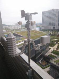
For this project, I’ll be using my Raspberry Pi 2, although you could certainly use your laptop or desktop system instead. I simply went with the Pi 2 for it’s small form factor and ease of maneuvering in space constrained places.

I’ll also be using my Logitech C920 webcam (that is plug-and-play compatible with the Raspberry Pi) along with the Raspberry Pi camera module. Again, if you decide to use your laptop/desktop system, you can simply hook-up multiple webcams to your machine — the same concepts discussed in this post still apply.

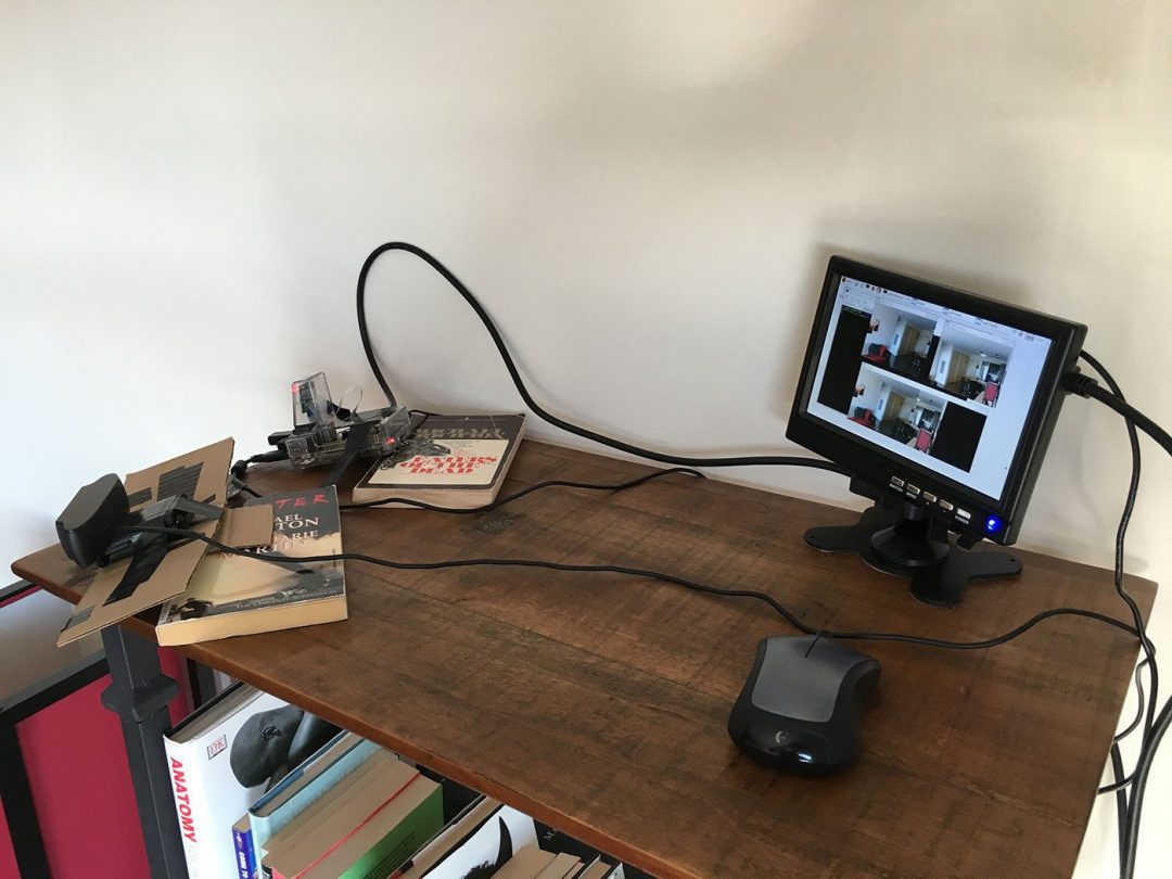
Below you can see my setup:

Figure 1: My the Raspberry Pi 2 + USB webcam + Pi camera module setup.

Figure 1: My the Raspberry Pi 2 + USB webcam + Pi camera module setup.

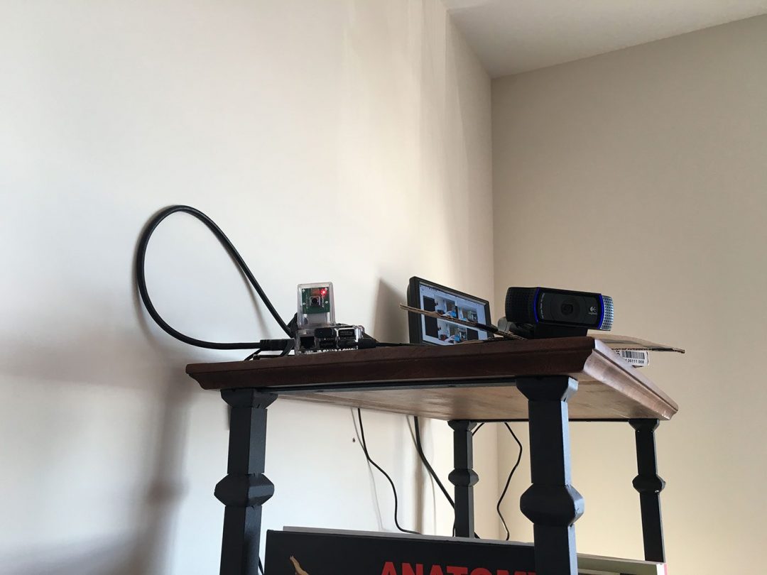
Here is another angle looking up at the setup:

Figure 2: Placing my setup on top of a bookcase so it has a good viewing angle of my apartment.

Figure 2: Placing my setup on top of a bookcase so it has a good viewing angle of my apartment.

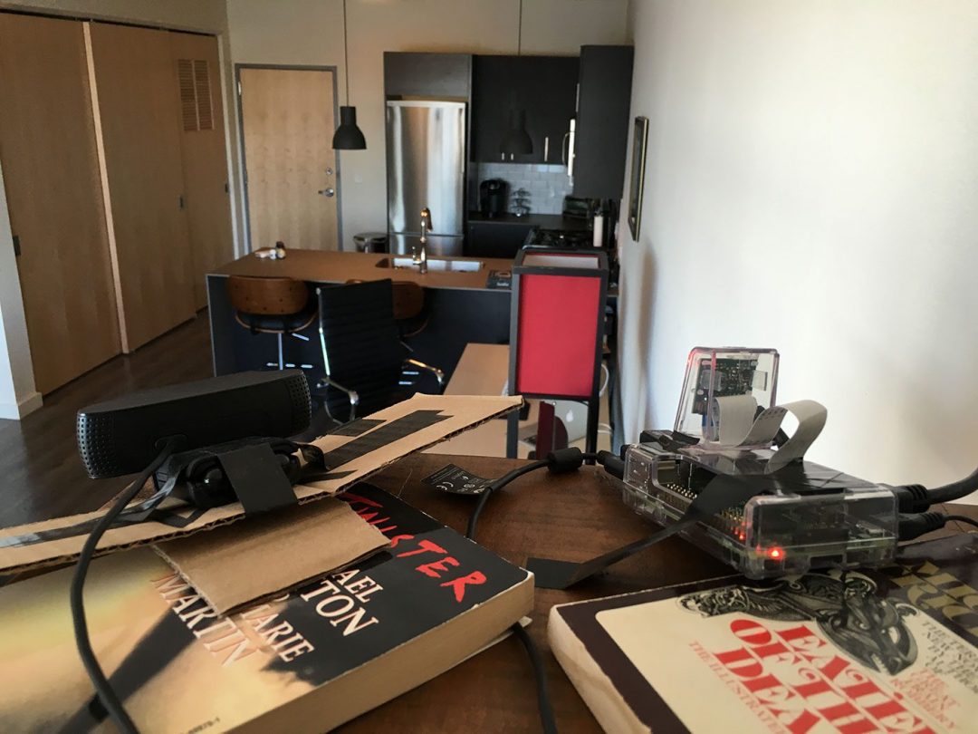
The setup is pointing towards my front door, kitchen, and hallway, giving me a full view of what’s going on inside my apartment:

Figure 3: Getting ready for real-time panorama construction.

Figure 3: Getting ready for real-time panorama construction.

The goal is to take frames captured from both my video streams, stitch them together, and then perform motion detection in the panorama image.

Constructing a panorama, rather than using multiple cameras and performing motion detection independently in each stream ensures that I don’t have any “blind spots” in my field of view.

Project structure

Before we get started, let’s look at our project structure:

As you can see, we have defined a pyimagesearch  module for organizational purposes. We then have the basicmotiondetector.py  implementation from last week’s post on accessing multiple cameras with Python and OpenCV. This class hasn’t changed at all, so we won’t be reviewing the implementation in this post. For a thorough review of the basic motion detector, be sure to read last week’s post.

We then have our panorama.py  file which defines the Stitcher  class used to stitch images together. We initially used this class in the OpenCV panorama stitching tutorial.

However, as we’ll see later in this post, I have made a slight modifications to the constructor andstitch  methods to facilitate real-time panorama construction — we’ll learn more about these slight modifications later in this post.

Finally, the realtime_stitching.py  file is our main Python driver script that will access the multiple video streams (in an efficient, threaded manner of course), stitch the frames together, and then perform motion detection on the panorama image.

Updating the image stitcher

In order to (1) create a real-time image stitcher and (2) perform motion detection on the panorama image, we’ll assume that both cameras are fixed and non-moving, like in Figure 1above.

Why is the fixed and non-moving assumption so important?

Well, remember back to our lesson on panorama and image stitching.

Performing keypoint detection, local invariant description, keypoint matching, and homography estimation is a computationally expensive task. If we were to use our previous implementation, we would have to perform stitching on each set of frames, making it near impossible to run in real-time (especially for resource constrained hardware such as the Raspberry Pi).

However, if we assume that the cameras are fixed, we only have to perform the homography matrix estimation once!

After the initial homography estimation, we can use the same matrix to transform and warp the images to construct the final panorama — doing this enables us to skip the computationally expensive steps of keypoint detection, local invariant feature extraction, and keypoint matching in each set of frames.

Below I have provided the relevant updates to the Sticher  class to facilitate a cached homography matrix:

The only addition here is on Line 11 were I define cachedH , the cached homography matrix.

We also need to update the stitch  method to cache the homography matrix after it is computed:

On Line 19 we make a check to see if the homography matrix has been computed before. If not, we detect keypoints and extract local invariant descriptors from the two images, followed by applying keypoint matching. We then cache the homography matrix on Line 34.

Subsequent calls to stitch  will use this cached matrix, allowing us to sidestep detecting keypoints, extracting features, and performing keypoint matching on every set of frames.

For the rest of the source code to panorama.py , please see the image stitching tutorial or use the form at the bottom of this post to download the source code.

Performing real-time panorama stitching

Now that our Stitcher  class has been updated, let’s move on to to therealtime_stitching.py  driver script:

We start off by importing our required Python packages. The BasicMotionDetector  andStitcher  classes are imported from the pyimagesearch  module. We’ll also need theVideoStream  class from the imutils package.

If you don’t already have imutils  installed on your system, you can install it using:

If you do already have it installed, make sure you have upgraded to the latest version (which has added Python 3 support to the video  sub-module):

Lines 14 and 15 then initialize our two VideoStream  classes. Here I assume that leftStream  is a USB camera and rightStream  is a Raspberry Pi camera (indicated byusePiCamera=True ).

If you wanted to use two USB cameras, you would simply have to update the stream initializations to:

The src  parameter controls the index of the camera on your system.

Again, it’s imperative that you initialize leftStream  and rightStream  correctly. When standing behind the cameras, the leftStream  should be the camera to your lefthand side and the rightStream  should be the camera to your righthand side.

Failure to set these stream variables correctly will result in a “panorama” that contains only one of the two frames.

From here, let’s initialize the image stitcher and motion detector:

Now we come to the main loop of our driver script where we loop over frames infinitely until instructed to exit the program:

Lines 27 and 28 read the left  and right  frames from their respective video streams. We then resize the frames to have a width of 400 pixels, followed by stitching them together to form the panorama. Remember, frames supplied to the stitch  method need to be supplied in left-to-right order!

In the case that the images cannot be stitched (i.e., a homography matrix could not be computed), we break from the loop (Lines 41-43).

Provided that the panorama could be constructed, we then process it by converting it to grayscale and blurring it slightly (Lines 47 and 48). The processed panorama is then passed into the motion detector (Line 49).

However, before we can detect any motion, we first need to allow the motion detector to “run” for a bit to obtain an accurate running average of the background model:

We use the first 32 frames of the initial video streams as an estimation of the background — during these 32 frames no motion should be taking place.

Otherwise, provided that we have processed the 32 initial frames for the background model initialization, we can check the len  of locs  to see if it is greater than zero. If it is, then we can assume “motion” is taking place in the panorama image.

We then initialize the minimum and maximum (x, y)-coordinates associated with the locations containing motion. Given this list (i.e., locs ), we loop over the contour regions individually, compute the bounding box, and determine the smallest region encompassing all contours. This bounding box is then drawn on the panorama image.

As mentioned in last week’s post, the motion detector we use assumes there is only oneobject/person moving at a time. For multiple objects, a more advanced algorithm is required (which we will cover in a future PyImageSearch post).

Finally, the last step is to draw the timestamp on panorama and show the output images:

Lines 82-86 make a check to see if the q  key is pressed. If it is, we break from the video stream loop and do a bit of cleanup.

Running our panorama builder + motion detector

To execute our script, just issue the following command:

Below you can find an example GIF of my results:
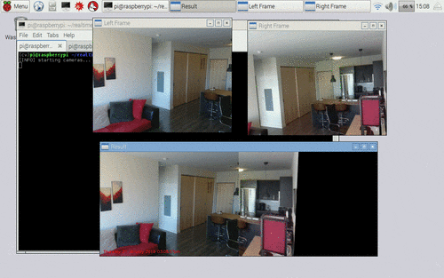
Figure 4: Applying motion detection on a panorama constructed from multiple cameras on the Raspberry Pi, using Python + OpenCV.

Figure 4: Applying motion detection on a panorama constructed from multiple cameras on the Raspberry Pi, using Python + OpenCV.

On the top-left we have the left video stream. And on the top-right we have the right video stream. On the bottom, we can see that both frames have been stitched together into a single panorama. Motion detection is then performed on the panorama image and a bounding box drawn around the motion region.

The full video demo can be seen below:

A DIY low-cost LoRa gateway based on pcDuino

$
0
0

Thanks to this open source project which uses the Raspberry Pi as Lora gateway and Arduino as Lora node device. We port this project to pcDuino and send the received data from Lora node to LinkSpriteIO. The basic architecture is shown as the following diagram.

There is an Arduino Lora node to read the sensor’s data and send it to pcDuino Lora gateway. After pcDuino Lora gateway recevice the data and it will send it to LinkSpriteIO which is our IoT cloud.

The following content, I will introduce the details of how to DIY a low-cost Lora gateway with pcDuino and Arduino.

Required

pcDuino lora gateway

  • pcDuino8 Uno x 1
  • LoRa module x 1
  • Linker cable x 1
  • Dupont Line x 2

Arduino lora node

  • Arduino Uno x 1
  • LoRa modulex 1
  • Linker cable x 4
  • Dupont Line x 2

Steps

1. Assemble the hardware

  • According to the following pins map table to connect the lora module and pcDuino or Arduino
Lora module pins Arduino Pins pcDuino Pins
SCK 13 13
MISO 12 12
MOSI 11 11
NSS 10 10
VCC 3.3V 3.3V
GND GND GND

Arduino Lora node

pcDuino Lora Gateway

2. Program Arduino Uno

  • Download the Arduino program from github
  • Use Arduino IDE to open the Arduino_LoRa_node project in examples folder
  • Upload this program to Arduino Uno
  • Open Serial Monitor to check the message

3. Program on the pcDuino8 Uno

Create device on LinkSpriteIO

  • Go to www.linksprite.io and sign up
  • Enter your Email and password to create a new account
  • Go to My Account to get your own API Key.
  • Click My Device, and choose Create DIY Device.

  • Click the created device icon and get the DeviceID **.

Download the source code

  • Access to the pcDuino8 Uno Ubuntu system Note: user name and password are all: linaro:
  • git clone https://github.com/YaoQ/pcduino-lora-AP
    cd pcDuino-lora-AP/pcduino-gateway
    make
  • Use your own deviceID and apikey to update the line 27 and 28 in LinkSpriteIO_Post.py
  • 26 # Use your own deviceID and apikey
     27 deviceID="xxxxxxxxxx"
     28 apikey = "xxxxxxxxxxxxxxxxxxxxxxxxxxxxxxxxxxxx"
  • 4. Test

    To make it simple, we just use random number to simulate the temperature value and send it periodically to pcDuino lora gateway. Then pcDuino Lora gateway will post data to LinkSpriteIO.

  • ./pcduino-gateway | python LinkSpriteIO_Post.py
  • On Arduino side:

    On pcDuino side:

    On LinkSpriteIO side:

Wireless All Sky Camera

$
0
0
Picture of Wireless All Sky Camera

An all sky camera is a device designed to take pictures of the entire sky over a certain amount of time, usually to monitor meteor showers or other astronomical phenomena.

I built mine to monitor the northern lights. I live in the Yukon and we sometimes get beautiful aurora displays during the night. However, I also have a day time job and I need my 8 hours of sleep. I created this camera to record a movie of the entire night. That way, I can replay the movie in the morning and never miss any aurora night.

Step 1: Requirements and materials

Picture of Requirements and materials

My requirements for this camera are the following:

  • needs to photograph most of the sky
  • needs high sensitivity to low light
  • should be weather proof
  • no wires should run to the house
  • needs to be autonomous
  • needs to create a movie from pictures and upload it to the internet
  • needs to start at dusk and stop at dawn

After thinking about it for a while, I decided that the device should include its own computer and send the pictures using wifi. As for the camera, I decided to use an astronomy camera that would be small enough and was powered over USB.

Here’s the list of materials:

  • ASI224MC camera from ZWO (ASI120MC or MM works too and is cheaper)
  • wide angle lens Arecont 1.55 (It gives a wider field of view than the lens that comes with the camera)
  • Raspberry Pi 2 (or 3)
  • 64 GB micro SD card
  • Wifi module (no need if Raspberry Pi 3)
  • Short right angle USB cable
  • 4″ ABS pipe with end caps
  • Acrylic dome

I thought about adding a dew heater but after a few month of testing, I never got any frost on the acrylic dome. This is possibly due to the heat produced by the raspberry pi itself.

Step 2: Wiring

Picture of Wiring
20160123_120027.jpg

In this instructable, I will assume that you already have raspbian installed on the SD card.

The wiring is relatively easy. Plug the USB cable to the camera on one side and the raspberry pi on the other. Plug the wireless dongle into one of the 3 remaining USB ports of the pi. Insert the micro SD card in its slot and plug the raspberry pi to its 5V adapter.

In order to keep things tidy, you can fix your camera and computer onto a plywood board like I did on the picture.

Step 3: Build the enclosure

Picture of Build the enclosure
20160124_151541.jpg

The enclosure is made of a 4″ ABS pipe, a flat end cap and a threaded end cap with its lid.

The flat cap goes on top and is drilled to the diameter of the camera. The threaded cap goes at the bottom and a hole (for the extension cord) is drilled in the centre of the lid.

The acrylic dome can be fixed onto the top end using weather proof silicon. I used an acrylic ring but it makes things more complex than they need to be.

You can now fix the enclosure onto your deck, your roof or any other location with a good view of the sky.

Step 4: Software

Picture of Software

In order to capture images with the camera, we need to run a program in the terminal. ZWO provides an SDK in order for developers to communicate with the camera. Using this SDK, I modified one of their C++ example and compiled it for the raspberry pi. Here’s a list of dependencies that need to be installed in order to get the program running.

  • OpenCV to capture the image of the sky (You can get a compiled version here)
  • Sunwait to calculate the civil twilight of your location. There is a compiled version in the archive. Make sure you copy it to your path:
    sudo cp ~/allsky/sunwait /usr/local/bin
  • Required dependencies:
    sudo apt-get update && sudo apt-get install libusb-dev libav-tools gawk lftp entr imagemagik

To make things easy, I have attached an archive. Extract it at /home/pi/allsky.

From the lib folder, you will need to run this in order to use the camera without being root:
sudo install asi.rules /lib/udev/rules.d

You will also need to add libASICamera2.so to your library:
sudo cp ~/allsky/lib/armv7/libASICamera2* /usr/local/lib

Another thing you will need to do in order to automate everything is to run the main program on startup of the pi. You can open ~/.config/lxsession/LXDE-pi/autostart and add this line:
@xterm -hold -e ~/allsky/allsky.sh

Remember to set your wifi connection in order for the pi to upload videos.

allsky.sh contains all the parameters you might want to play with: GPS coordinate, white balance, exposure and gain.

Step 5: Collect images

Picture of Collect images
aurora2.png

Now that the raspberry pi is ready, you can plug your all sky camera. The startup script should call allsky.sh which in turn calls the binary file named “capture”. It will determine if it’s day time or night time. In case it’s night time, the capture will start and take a picture every 5 seconds (or whatever value you set in allsky.sh). At the end of the night, the capture will stop and avconv will stitch them together and upload a video to your website using FTP.

Step 6: Watch your time lapse videos

Picture of Watch your time lapse videos

The video produced by avconv should weigh between 30 and 50 mb depending on the length of the night (here in the Yukon, we can get from 18 hours to 0 hours of night time) and should be viewable on any web browser.

In the event that you find something interesting in the video, you can access the individual images on the raspberry pi. They will be in a folder named after yesterday’s date.

Here’s a page showing my own videos with almost all night archived starting January 18th 2016. Some have beautiful northern light, others have clouds, snow or rain.

http://www.instructables.com/id/Wireless-All-Sky-Camera/

How to burn system for pcDuino9s

$
0
0

Wiring Instructions of pcDuino9s

The jumper cap is connected to the OTG_ID mode as shown below. At this time, the USB port is USB HOST mode, which is used to connect the mouse, keyboard, U disk and other peripherals.

The jumper cap is connected to the VBUS_IN mode as shown below. At this time, the USB port is used as the brush port, USB Device mode, connected to the computer.

Note:

Please don’t connect the power supply of RK3288 board when you brush the system.


 Install Deiver

Click “\Linux\Tools\DriverAssitant_v4.5\DriverInstall.exe” install driver, as shown below.

After the installation is successful, you will see a massage Box pop-up as shown in the figure below.

Note:

If you has ever brushed Android system for RK3288 board or RK3328 board, you can not install the driver.


Debian flash operation

  1. Run “Linux\Tools\AndroidTool_Release_v2.39\AndroidTool.exe” select “Downlaod Image” table. as shown below.
  2. Move the mouse to boot and right_click, select load config.Choose the file onefile.cfg, and path is…\Linux\Images\Debian\RK3288-Debian-10.4inches-20180209\onefile.cfg
  3. Hold press “BOOT” key, than press “reset” key. wait for AndroidTool find MASKROM device release “BOOT” key.
  4. Click “Run” button for flash Debian. as shown below.


Android flash operation

  1. Run “Linux\Tools\AndroidTool_Release_v2.39\AndroidTool.exe” select “Upgrade Firmware” table.
  2. Click “Firmware” button load “Linux\Images\Android\RK3288-Android-10.4inches-20180209\RK3288-android-10.4inches.img” Android image file.
  3. Hold press “BOOT” key, than press “reset” key. wait for AndroidTool find MASKROM device release “BOOT” key.
  4. Click “Upgrade” button for flash Android.


Erase flash operation

When Debian or Android display bad, must erase flash before flash Debian or Android

  1. Run “Linux\Tools\AndroidTool_Release_v2.39\AndroidTool.exe” select “Upgrade Firmware” table.
  2. Click “Firmware” button load “Linux\Images\Android\RK3288-Android-10.4inches-20180209\RK3288-android-10.4inches.img” Android image file.
  3. Hold press “BOOT” key, than press “reset” key. wait for AndroidTool find MASKROM device release “BOOT” key.
  4. Click “EraseFlash” button for erase flash.

Data package for burning system


Viewing all 15 articles
Browse latest View live